
The Transition Area (see Figure 4) includes 12 square-mile PLSS sections, extending generally east from Area A for four miles, with one of the sections (T13N, R69W, Section 17) lying just north of Area A (T13N, R69W, Section 20). The ground surface slopes down to the northeast from the LSB area at a moderate slope toward Lone Tree Creek, losing 200 feet of elevation over 0.6 miles. Depths to the water table decrease from approx. 84 feet at the northeast corner of Area A to less than 10 feet below ground surface (bgs) near the creek. The ground surface slopes downward to the east from the LSB area at a gentler slope of about 100 feet in 0.7 miles with the depth to the water table increasing from approximately 85 feet near LSB 3 to 162 feet bgs at MW89 located 0.9 miles east of LSB 3.
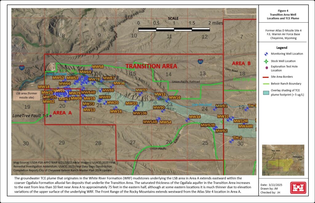
A PDF copy of Figure 4 can be opened here (link). Click the Site Overview link in the ribbon above for a smaller-scale map showing the entire site and the City of Cheyenne.
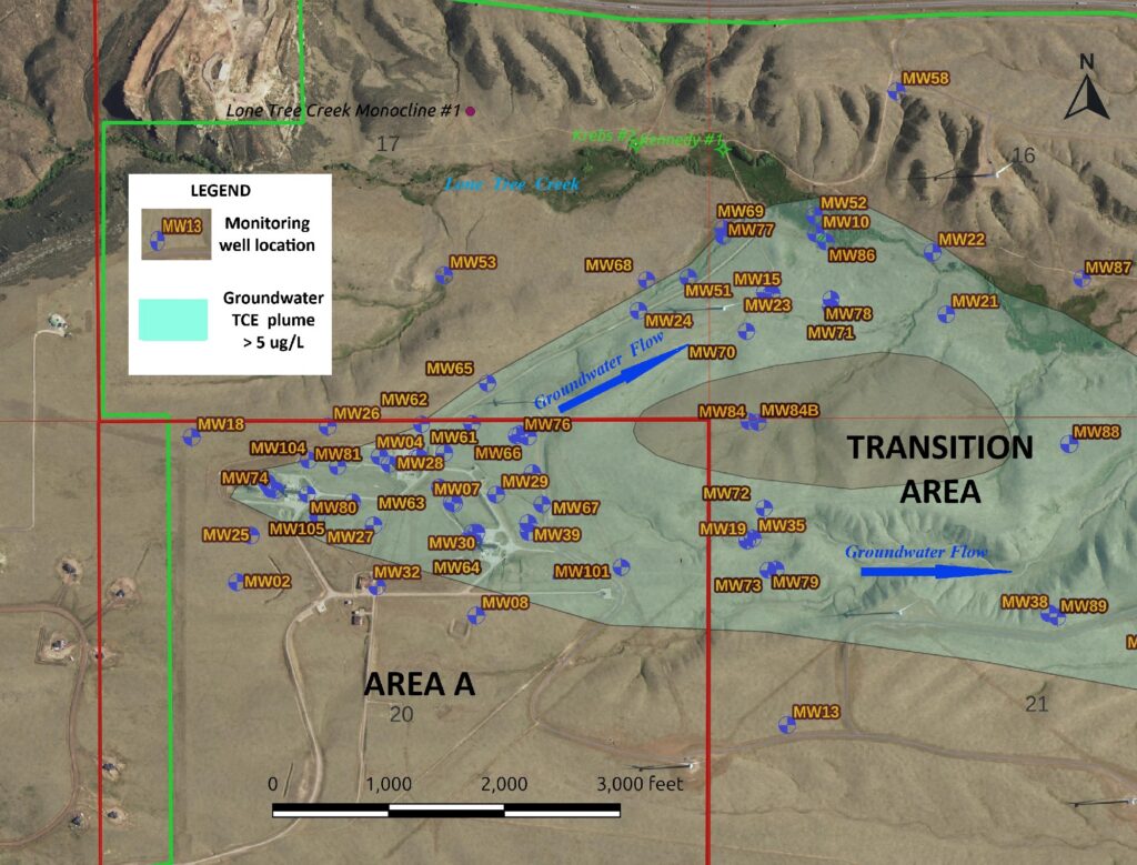
Groundwater flow is eastward and northeastward from Area A into the Transition Area, and the TCE plume originating at the LSB area in Area A has been mapped entering the Transition Area along two vectors, one to the northeast from the LSBs and one directly east from the LSB area. This plume bifurcation immediately northeast and east of the LSB area is present in the saturated portions of both the basal Ogallala Formation alluvial fan deposits and the underlying upper White River Formation (WRF) mudstones. The TCE plume vertical extent within the upper saturated WRF along these two limbs of the plume varies between about 85 and 125 feet at the northeast corner of Area A and decreases to about 65 feet near Lone Tree Creek (0.6 miles northeast of the LSB area); along the east limb of the plume the plume thickness (in the WRF) decreases eastward to about 50 feet near MW88 (0.9 miles east of the LSB area). The plume bifurcation immediately downgradient from the LSB area appears to be directly related to two fairly small paleo-channels or buried drainages that are present at the contact between the two formations.
The northeast-extending paleochannel is about 500 feet across and is incised into the top of the WRF sediments about 60 feet at its thickess extents, while the east-trending paleochannel (located south of the northeast one) is about 1,000 feet across and between 10 and 40 feet thick in the area extending one mile east of the LSB area. At this location close to the Rocky Mountain front range, the paleochannels on the surface of the WRF were filled by the initial deposition of the coarser Ogallala alluvial fan, and eventually completely buried by the alluvial fan progradation eastward during the Miocene period.
The current saturated thickness of the basal Ogallala alluvial fan sediments within the paleochannel extending to the northeast is less than the vertical depth of the buried channel, ranging from a few feet at the northeast corner of Area A to about 10 feet near Lone Tree Creek 3/4 mile northeast of the LSB area. The saturated thickness within the paleochannel extending to the east is more commensurate with the depth of the buried channel, ranging from about 13 feet at MW67 to approximately 40 feet one mile east of the LSB area, between MW88 and MW89.
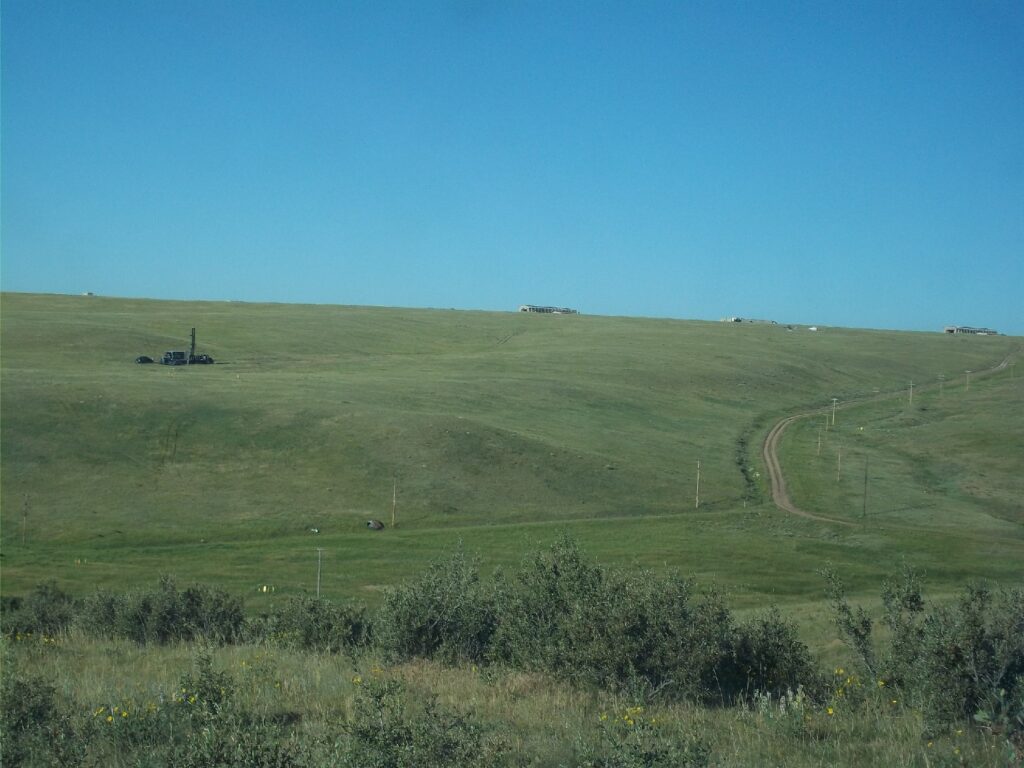
The plume bifurcation has been confirmed by consistent groundwater sample results over several years by samples from MW84 and MW84B, located between the two arms of the plume. These two triple-nested wells are screened at various depths throughout the vertical thickness of the plume, as measured in nearby monitoring wells within the area. TCE has not been detected in groundwater samples collected from MW84 and MW84B. This observation supports the hypothesis that the TCE groundwater contamination (likely at high concentrations) initially migrated along the paleochannels extending to the east and northeast from the LSB Area and migrated downward into the upper WRF in areas contiguous to and beneath these paleochannels.
This interpretation is supported by the fact that MW84 and MW84B are located only 3,000 feet downgradient from the LSB area, approximately midway between the east- and northeast-oriented paleochannels, yet TCE does not appear to have migrated through the saturated WRF material to this location during the more than 60 years since the releases occurred. In contrast, TCE was detected in groundwater collected from the former DoD production well, Hall No. 3 stock well, in 2002, only 40 years following the release(s). The Hall No. 3 stock well is located within the northeast paleochannel, 4,000 feet from the LSB area, very close to MW10 and MW86 (shown on Map 2 below). This well produced water from the basal Ogallala (i.e., paleochannel) deposits and the underlying White River Formation. The Hall No. 3 well was sealed in 2003 following removal of the pump, and it was plugged with bentonite-cement grout in 2008.
At MW84/MW84B the water table is about 20 feet below the top of the WRF; therefore, the top of the WRF at this location represents a buried upland area situated between the saturated buried paleochannels. The average groundwater flow velocity within the upper WRF (composed of clayey silts, silty clays, and mudstones) has been estimated at an average of 70 feet per year, with a range of 3 to 144 ft/year. Based on the absence of TCE at the MW84/MW84B location, the groundwater flow velocity in the saturated WRF along a vector extending from LSB 2 appears to be less than 45 ft/year.
The two arms of the plume merge together in the Transition Area about 0.8 miles east of the LSB area, around the location of nested monitoring well MW88 (see Map 2 below). In this area (MW88) the vertical thickness of the TCE plume in the upper WRF is approximately 50 feet. East of MW88 the saturated thickness in the Ogallala Formation alluvial fan strata and by default the Ogallala TCE plume increases from about 40 ft to 75 feet at MW106, located 1.8 miles east of the LSB area. TCE has been detected in Ogallala aquifer groundwater samples at MW106 at 200 µg/L.
There are six triple-nested wells installed in the east half of the Transition Area at four locations but only one of these locations (MW92/MW92B) is within the TCE plume (see Figure 4 above). Installation of a few additional nested monitoring wells would allow greater delineation of the plume in this area. The Ogallala saturated thickness at the east edge of the Transition Area varies from 23 ft at MW92/MW92B to 83 feet at MW91. A topographic high on the surface of the WRF at MW92/MW92B limits the Ogallala Formation saturated thickness at this location. The highest TCE concentration detected in groundwater samples from MW92/MW92B is 70 µg/L in a sample from the Ogallala aquifer (Fall 2023 sample event); this sample was collected from the shallowest well at this location, which screens a perched water zone just above a 9-ft thick hard siltstone/claystone layer that is present about 16 feet above the WRF contact (encountered at 313 ft bgs). The static water level in this well (MW92B-288) is 272 feet bgs, while the true depth to the water table in the other wells at this location is approximately 313 ft bgs.
Webpage updated 6/24/2026